CAD Blocks categories
 3D models
 home furniture
 sanitary ware - bathrooms
 professional equipment
 doors and windows
 people and animals
 plants and trees
 vehicles - transports
 architectural details
 mechanical - electrical
 urban planning - civil works
 safety health construction
 accessible design
 drawing sheet
 signals
 construction machinery
 accessories and objects
 maps and street maps
![]() Technical drawing sheets in CAD feature title blocks, tolerance and projection blocks, standardized sheet sizes (ISO and ANSI), and shields, ensuring clarity and consistency in engineering and architectural designs.
Technical drawing sheets in CAD feature title blocks, tolerance and projection blocks, standardized sheet sizes (ISO and ANSI), and shields, ensuring clarity and consistency in engineering and architectural designs.
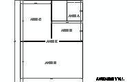
Drawing Page - Standard Drawing Sheet Sizes
Each drawing page in a CAD file adheres to standardized dimensions to ensure consistency and compatibility across industries. According to the ASME Y14.1 standard, drawing sheet sizes in the United States primarily follow the ANSI (American National Standards Institute) format. Globally, many projects also utilize ISO (International Organization for Standardization) formats. These standards ensure clarity in communication and uniformity in technical documentation.
Below is a comparison of common ISO and ANSI sheet sizes, with their respective dimensions:
- ISO A4: 210 x 297 mm (8.27 x 11.69 inches) ANSI Equivalent: ANSI A (8.5 x 11 inches)
- ISO A3: 297 x 420 mm (11.69 x 16.54 inches) ANSI Equivalent: ANSI B (11 x 17 inches)
- ISO A2: 420 x 594 mm (16.54 x 23.39 inches) ANSI Equivalent: ANSI C (17 x 22 inches)
- ISO A1: 594 x 841 mm (23.39 x 33.11 inches) ANSI Equivalent: ANSI D (22 x 34 inches)
- ISO A0: 841 x 1189 mm (33.11 x 46.81 inches) ANSI Equivalent: ANSI E (34 x 44 inches)
While ISO sizes are based on a consistent aspect ratio of 1:√2, ANSI sizes differ slightly in proportion but are designed to align with the standard letter size (8.5 x 11 inches) for easier integration in office workflows.
Using these standardized sizes in CAD block libraries ensures that drawings can be easily reproduced, scaled, and understood across various platforms and regions. Depending on the project’s requirements, specific sizes like A4/ANSI A or A1/ANSI D may be preferred for documentation and production.
Title Block
The title block is an essential component of technical drawings, providing a standardized area for essential project details. According to the ASME Y14.1 standard, the title block is located in the lower right-hand corner of the drawing sheet and typically includes the following information:
- Project Name: Clearly identifies the purpose or subject of the drawing.
- Drawing Number: A unique identifier for the specific sheet, essential for documentation and retrieval.
- Revision History: Tracks changes made to the drawing over time, ensuring accurate version control.
- Author’s Information: Includes the drafter's or designer's name, signature, and date of creation.
- Approval Information: Space for signatures and dates of approval by relevant authorities.
Title blocks also often include additional details such as the company logo, scale of the drawing, and any applicable disclaimers or standards used in the design. These elements ensure that the drawings are both professional and compliant with engineering documentation practices.
Title block dimensions can vary depending on the size of the drawing sheet. For example, in ANSI sheet sizes:
- ANSI A (8.5 x 11 inches): Title block width is typically 4 inches, occupying approximately 1/3 of the horizontal space.
- ANSI B (11 x 17 inches): Title block expands proportionally, often measuring 5 to 6 inches wide.
- ANSI E (34 x 44 inches): Larger title blocks with additional sections for project codes and extended revision details.
In addition to size variations, title blocks in larger sheets often incorporate spaces for multiple approvals, extended revision logs, and project-specific codes, making them adaptable for a range of disciplines such as architecture, civil engineering, and mechanical design.
By following the ASME Y14.1 guidelines, title blocks ensure consistency, clarity, and professionalism across all CAD designs, simplifying collaboration and documentation in large-scale projects.
Tolerance and Projection Blocks for A, B, C, D, E, F, H, G, and J Sizes
Tolerance and projection blocks are critical elements in engineering drawings, ensuring dimensional accuracy and clarity of projection methods. These blocks follow the guidelines established by the ASME Y14.1 standard, providing uniformity across various drawing sizes.
The primary purposes of tolerance and projection blocks include:
- Tolerance specifications: Indicating acceptable dimensional variations for manufactured parts to ensure proper assembly and functionality.
- Projection methods: Defining the type of projection used in the drawing, such as first-angle or third-angle projection, essential for interpreting the design correctly.
- Placement and standardization: These blocks are usually integrated into the title block or placed adjacent to it for easy reference.
The ASME Y14.1 standard specifies these blocks for multiple sheet sizes, ensuring compatibility with both smaller sizes like ANSI A (8.5 x 11 inches) and larger formats such as ANSI E (34 x 44 inches). Below is a breakdown of the standard sizes:
- ANSI A to ANSI E: Commonly used for general engineering and architectural drawings.
- Special sizes (F, H, G, J): These sizes accommodate detailed or extended tolerance specifications required in complex designs.
For example, tolerance and projection blocks for ANSI E sheets are designed to handle the increased complexity and scale of larger projects, offering sufficient space for additional annotations and dimensioning data.
Incorporating tolerance and projection blocks ensures consistency, reduces errors, and facilitates seamless communication across industries, including aerospace, automotive, and civil engineering.
Administrations' Shields
Shields, or emblems, are used to indicate official authority on engineering and architectural CAD drawings. These might include a city’s or organization's logo to signify approval. For example, an emblem might measure 0.25 meters (9.84 inches) in diameter on a title block in a .dwg file.


