CAD Blocks categories
 3D models
 home furniture
 sanitary ware - bathrooms
 professional equipment
 doors and windows
 people and animals
 plants and trees
 vehicles - transports
 architectural details
 mechanical - electrical
 urban planning - civil works
 safety health construction
 accessible design
 drawing sheet
 signals
 construction machinery
 accessories and objects
 maps and street maps
ANSI C Drawing Sheet Size ASME Y14.1 - Free CAD Download

size: 50 kb
category: drawing sheets and presentations
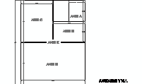
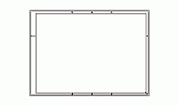
description: Technical drawing sheet in ANSI C size, compliant with ASME Y14.1 standards. The sheet measures 22 inches by 17 inches (558.8 mm x 431.8 mm) in a horizontal layout. It features labeled zones with alphanumeric identifiers along the borders, ensuring precise referencing for large-scale designs. A standardized title block is located in the bottom-right corner, allowing for project details, scale, and revision information.
file extension: .dwg CAD - AutoCAD software
Understanding ANSI C Size Sheet Standards
Overview of ANSI C Drawing Sheet Features
The ANSI C drawing sheet, governed by ASME Y14.1 standards, features a layout that ensures professional and consistent engineering documentation. This size offers a flat surface measuring 22 inches by 17 inches (558.8 mm x 431.8 mm). Key sections include the title block, projection block, and defined margins, essential for clear technical drawings.
Dimensions and Equivalency in Standards
According to ANSI standards, the C-size sheet measures 22 x 17 inches, frequently used for detailed designs. In ISO equivalents, this closely aligns with the A2 format, measuring 594 mm by 420 mm. The metric adaptation ensures compatibility across diverse engineering frameworks worldwide.
Applications of ANSI C Size in Industries
Widely adopted in mechanical engineering, architecture, and technical drafting, the ANSI C sheet accommodates intricate diagrams. Its manageable size and scalability make it ideal for educational purposes, industrial machinery designs, and architectural layouts. Professionals rely on it for precise detailing and space-efficient designs.
Frequently Asked Questions about ANSI C Size
Q: What size and format is ASME Y14.1 drawing sheet?
A: ASME Y14.1 specifies ANSI C sheets as 22 x 17 inches, formatted for technical documentation.
Q: What is the ISO equivalent of ANSI C size?
A: The closest ISO counterpart is the A2 size, measuring 594 mm by 420 mm.
Q: What are the standard ANSI dimensions?
A: ANSI sizes range from A (8.5 x 11 inches) to E (34 x 44 inches), each suited for specific documentation needs.
Q: What is ANSI A drawing size?
A: The ANSI A size, commonly used for letters, is 8.5 x 11 inches.
Q: What is ANSI Y14.5 drawing standards?
A: These standards focus on dimensioning and tolerancing practices for engineering drawings.
Evolution and Relevance of ANSI C Sheets
Introduced under ASME Y14.1 standards, ANSI C sheets have evolved alongside technical drafting tools. Initially used for hand-drawn designs, they are now integral to CAD platforms, ensuring accuracy and cross-border standardization in engineering and architectural documentation.
Step-by-Step Guide to Using ANSI C Sheets for AutoCAD Presentations
AutoCAD provides a comprehensive set of tools to utilize ANSI C drawing sheets effectively in presentations. Follow these steps to set up and use an ANSI C size sheet for professional outputs:
Step 1: Create a Template. Start by setting up an ANSI C-sized template (22 x 17 inches). Access the Page Setup Manager from the Output tab ➢ Plot panel, and configure the layout to ANSI C dimensions. Name the layout for easy identification, such as "ANSI-C-Layout".
Step 2: Switch to Paper Space. Toggle to Paper Space by selecting the Layout tab. This allows you to manage title blocks, borders, and additional elements like viewports effectively.
Step 3: Insert Title Block. Use the INSERT command to add a title block into your layout. Ensure to configure the insertion point to 0,0,0 and keep the scale and rotation at default values. This step standardizes your presentation layout.
Step 4: Set Up Viewports. Add and configure viewports by using the Viewport panel. Adjust the scale to match your drawing needs (e.g., 1:1 or 1:50). Lock viewport settings to avoid accidental modifications.
Step 5: Finalize Presentation. Add annotations, dimensions, and other presentation elements within the defined viewport or directly in the layout. Use AutoCAD's Annotate tab to add labels and other text, ensuring readability and alignment with the ANSI C layout.
By following these steps, your ANSI C-sized AutoCAD drawings will meet professional presentation standards for engineering and architectural applications.


