CAD Blocks categories
 3D models
 home furniture
 sanitary ware - bathrooms
 professional equipment
 doors and windows
 people and animals
 plants and trees
 vehicles - transports
 architectural details
 mechanical - electrical
 urban planning - civil works
 safety health construction
 accessible design
 drawing sheet
 signals
 construction machinery
 accessories and objects
 maps and street maps
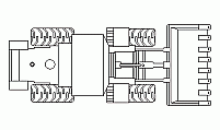
Motor Grader Plan View CAD Block

size: 13 kb
category: construction machinery
description: Motor grader in plan view
file extension: .dwg CAD - AutoCAD software
Detailed Motor Grader Drawing for CAD Designs
Understanding the Motor Grader Plan View
The motor grader plan view provides a top-down representation of this essential piece of construction equipment. This drawing, often referred to as a grader top view or grading machine plan drawing, showcases the layout and key dimensions of the machinery. It serves as a valuable reference for architectural and engineering projects, enabling precise placement in technical layouts.
Dimensions and Scaling of the Grader Plan
Common dimensions of motor graders include lengths of 240 inches (6.1 meters) and widths of 96 inches (2.4 meters), offering scalable flexibility for various project needs. To modify these sizes, use the scaling factor of 1 inch = 0.0254 meters or 1 meter = 39.37 inches. Apply precise commands in your CAD software to rescale the drawings, ensuring accurate representation in either measurement system.
Motor Grader Use in Technical Plans
Motor graders play a crucial role in construction and earthmoving projects. These plan views are frequently included in technical CAD layouts to optimize road leveling, grading, and other site preparation tasks. Their inclusion in graphical representations enhances the accuracy and functionality of engineering and architectural designs.
Customizing Your Motor Grader CAD Drawing
Adjustments to the grader's CAD layout can improve its fit within your specific project. To modify the design, use commands such as "explode" to break apart blocks, "stretch" to adjust dimensions, and "mirror" for symmetrical adjustments. Refining details ensures seamless integration with your construction equipment diagrams.
Integrating the Motor Grader with Other Equipment
The motor grader plan view complements other machinery blocks, such as excavators, loaders, and dump trucks, in comprehensive technical layouts. Together, these components create a robust visual for construction site planning and operational sequencing, essential for architectural and engineering professionals.


